

Introduction:Why VFD Maintenance Matters
Variable Frequency Drives(VFDs)—also known as AC drives,frequency inverters,or adjustable speed drives—are now installed by the millions across industrial plants,commercial buildings,and infrastructure systems worldwide.Yet a surprising number of these drives operate under a”run-to-failure”maintenance philosophy that leaves significant reliability and cost savings on the table.
Industry data consistently shows that over 60%of VFD failures are preventable through proper routine maintenance.A single unplanned drive failure can halt an entire production line,with downtime costs often 10–50 times the annual maintenance budget for that drive.
Part 1:Common VFD Fault Types and Alarm Code Reference
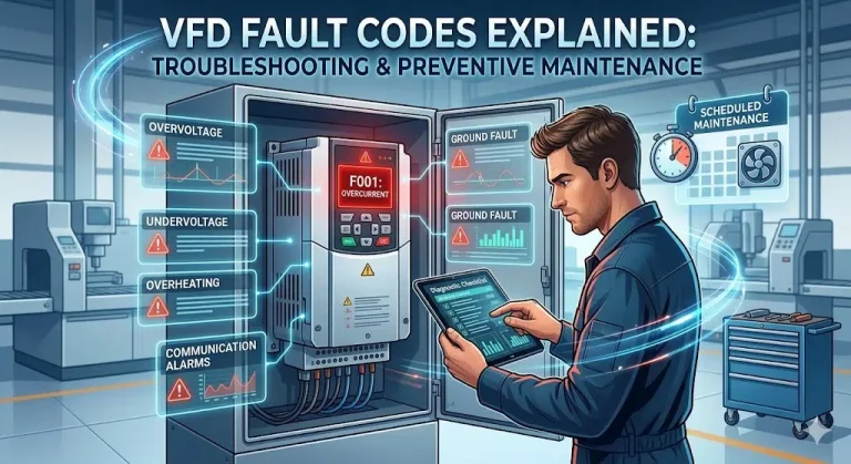
1.Overcurrent Fault(OC)
Overcurrent is the most frequently encountered VFD alarm,indicating that output current has exceeded the drive’s instantaneous overcurrent protection threshold.
Typical alarm codes by brand:ABB ACS series displays”2310 OVERCURRENT.”Siemens SINAMICS series shows”F0001.”Mitsubishi FR series indicates”E.OC1/E.OC2/E.OC3.”Yaskawa drives display”oC.”Delta drives show”oc.”Danfoss drives report”Alarm 4.”The numerical suffix typically differentiates the operating phase—OC1 during acceleration,OC2 during deceleration,and OC3 during constant-speed operation.
Systematic troubleshooting:Check for excessively short acceleration or deceleration ramp times.Use a megohm meter(500V DC)to measure phase-to-ground insulation resistance—healthy insulation should read above 5 MΩ.Inspect the driven equipment for mechanical binding.If the fault persists with the motor disconnected,the IGBT power module may be damaged.
2.Overvoltage Fault(OV)
Overvoltage faults indicate that the DC bus voltage has exceeded the drive’s overvoltage protection threshold,most commonly during motor deceleration when regenerative energy flows back into the drive.
Typical alarm codes:ABB shows”3210 DC OVERVOLT.”Siemens displays”F0002.”Mitsubishi indicates”E.OV1/E.OV2/E.OV3.”Danfoss reports”Alarm 7.”In a 380V/400V system,the normal DC bus voltage is approximately 540V DC with overvoltage protection typically set between 770–820V DC.
Key troubleshooting:Check whether the deceleration time is too short.Verify incoming supply voltage with a power quality analyzer.For applications with frequent braking duty(elevators,centrifuges),size the braking resistor for continuous duty or consider upgrading to an energy-regenerative drive.
3.Undervoltage Fault(UV/LV)
Undervoltage faults indicate the DC bus voltage has fallen below the minimum operating threshold.
Typical alarm codes:ABB shows”3220 DC UNDERVOLT.”Siemens displays”F0003.”Mitsubishi indicates”E.UV.”Yaskawa shows”Uv1/Uv2/Uv3.”Danfoss reports”Alarm 14.”
Primary causes include utility voltage sags and momentary power interruptions from large loads switching within the facility.Solutions include installing input line reactors,enabling the VFD’s ride-through function,or activating Kinetic Energy Buffering(KEB)mode.Also inspect the main circuit contactor contacts and DC bus electrolytic capacitors for aging.
4.Overtemperature Fault(OH/OT)
Overtemperature faults indicate the VFD heatsink or internal component temperature has exceeded the protective threshold—typically 85°C–95°C depending on the drive model.
Troubleshooting checklist:Verify cooling fan operation(fan life is typically 3–5 years).Clean heatsink fins using compressed air.Confirm adequate ventilation clearance—minimum 150 mm above and 100 mm below.Measure ambient temperature inside the enclosure.Review the carrier(switching)frequency setting—reducing carrier frequency from 8 kHz to 4 kHz can lower drive heat generation by 15%–25%.
5.Ground Fault(GF/EF)
Ground fault alarms indicate the VFD has detected excessive leakage current from one or more output phases to ground.
Diagnostic procedure:Disconnect motor cables and use a megohm meter to test phase-to-ground insulation resistance on each motor phase.Healthy insulation should exceed 5 MΩ.Motors idle in humid environments commonly experience insulation degradation recoverable by low-voltage heating.If external tests pass and the fault persists,inspect the VFD’s internal current transformers and leakage current detection circuitry.
6.Communication Fault(CE/CF)
Communication faults indicate the data link between the VFD and the supervisory controller(PLC,DCS,BMS,or SCADA)has been interrupted.
Common root causes include loose connections on Modbus,Profibus,Profinet,or EtherNet/IP cables;communication parameter mismatches(baud rate,node address,parity);missing bus termination resistors causing signal reflections;and electromagnetic interference.Use a protocol analyzer or oscilloscope to inspect signal waveform quality when other causes are ruled out.
Part 2:Complete Preventive Maintenance Schedule
Daily/Weekly Inspection
Daily inspections serve as the first line of defense.Walk-through checks should include visual confirmation that all VFD status indicators and displays show normal operation.Listen for abnormal sounds.Use an infrared thermometer to spot-check heatsink surface temperatures.Verify cabinet ambient temperature and humidity.Log key operating parameters—output current,voltage,frequency,and temperature—for trend analysis.
Monthly Maintenance
Clean cooling fans and intake/exhaust air filters using compressed air(maximum 4 bar,15 cm nozzle distance).Inspect and retorque all power and control terminal connections using a calibrated torque wrench.Verify cabinet door gaskets and seals.Record cumulative run hours and fan operating hours.
Quarterly Maintenance
With the VFD disconnected,measure input and output cable insulation resistance using a 500V DC megohm meter.Visually inspect DC bus electrolytic capacitors for bulging,leaking,or discoloration.Clean or replace cabinet cooling filters.Back up the complete VFD parameter set.
Annual Overhaul
Measure DC bus capacitor capacitance and ESR—replace if capacitance loss exceeds 20%.Inspect IGBT module thermal paste and reapply if degraded.Check all PCB connectors,relays,fuses,and batteries.Run manufacturer diagnostic self-test routines.Update firmware to the latest available version.
Part 3:20 Key Tips to Extend VFD Service Life
- Maintain control cabinet internal temperature between 25°C–35°C.Every 10°C increase above optimal cuts electrolytic capacitor life roughly in half.
- Install temperature and humidity sensors inside VFD cabinets.Keep relative humidity below 90%RH and install anti-condensation heaters in cold or humid environments.
- Position VFDs away from direct sunlight and radiant heat sources.
- Ensure adequate ventilation clearance—minimum 150 mm above,100 mm below,and 50 mm on each side.
- In dusty environments,use sealed NEMA 12/IP54 enclosures with cabinet air conditioners or air-to-air heat exchangers.
- In corrosive gas environments,specify drives with C4 or C5 conformal-coated PCBs or use positive-pressure ventilated cabinets.
- Mount VFDs in locations with vibration levels below 0.5G.Use vibration-isolating pads if needed.
- Install AC line reactors(3%–5%impedance)on the VFD input to suppress harmonics and buffer voltage transients.
- For motor cable runs exceeding 50 meters,install an output reactor or dV/dt filter to protect motor insulation.
- Use shielded power cables for VFD-to-motor connections and ground the cable shield at both ends.
- Maintain minimum 300 mm separation between power cables and signal/communication cables.
- Set the carrier frequency as low as the application’s noise requirements allow to reduce internal losses.
- Avoid frequently cycling VFD main power on and off—limit to no more than 3 power cycles per hour.
- Install appropriate surge protection devices(SPDs)on VFD input power lines.
- Establish a VFD asset register documenting installation date,run hours,maintenance history,and parameter backups.
- Set up proactive fan replacement alerts—typical fan life is 25,000–40,000 operating hours.
- Schedule capacitor health checks at the 5-year mark and every 2 years thereafter.
- Leverage built-in predictive maintenance features offered by major VFD manufacturers.
- Conduct regular training for maintenance personnel on operating procedures and emergency workflows.
- Maintain a critical spare parts inventory—fans,batteries,fuses,communication modules—to minimize MTTR.
Part 4:When to Replace or Upgrade Your VFD
Performance degradation signals:DC bus capacitor capacitance loss exceeding 20%,rising IGBT VCE(sat)values,increasing thermal alarms despite clean heatsinks,and escalating annual repair costs.
Technology upgrade drivers:Need for new communication protocols(Profinet,EtherCAT),functional safety features(STO,SS1,SLS),SiC MOSFET-based drives offering higher efficiency,or IoT connectivity and cloud-based analytics.
Product lifecycle management:Most VFD manufacturers designate products as End of Life(EOL)10–15 years after introduction,followed by a 5–7 year End of Service(EOS)period.Plan replacements before the EOS date to avoid extended downtime.
Part 5:Quick-Reference Fault Code Summary by Brand
ABB(ACS Series)uses a four-digit numeric code system:2310 for overcurrent,3210 for DC overvoltage,3220 for DC undervoltage,4210 for overtemperature,5210 for ground fault.
Siemens(SINAMICS Series)uses F-prefix(fault)and A-prefix(alarm)with four-digit codes:F0001 overcurrent,F0002 overvoltage,F0003 undervoltage,F0004 overtemperature.
Mitsubishi(FR Series)uses”E.”prefix codes:E.OC1/2/3 for overcurrent,E.OV1/2/3 for overvoltage,E.UV for undervoltage,E.OHT for overtemperature.
Yaskawa uses compact letter codes:oC for overcurrent,ov for overvoltage,Uv for undervoltage,oH for overtemperature.
Danfoss uses numbered alarms:Alarm 4 for overcurrent,Alarm 7 for overvoltage,Alarm 14 for undervoltage,Alarm 29 for heatsink overtemperature.
Conclusion
Reliable VFD operation directly impacts production uptime,product quality,and operating costs.Building a systematic fault diagnosis knowledge base combined with a disciplined preventive maintenance program is essential competency for every maintenance engineer and facility manager.
In the digital era,the convergence of IoT remote monitoring platforms,edge computing,and AI-driven predictive analytics is transforming VFD maintenance from reactive”fix-after-failure”to proactive”predict-and-prevent”—a shift that represents not just a technological advancement,but a fundamental evolution in maintenance philosophy.